Monday, November 23, 2020

How to calculate input impedance in LTSpice

 This post is a follow on to my previous post on output impedance. This time it is for calculating input impedance. Suppose we have a black box circuit that we will be sending a signal to. The black box could be Rx input pin of an RF transceiver IC, for example. 

We want to calculate Zin, the input impedance of the black box. In the case of input impedance, we'll add a 1V AC signal at the frequency of interest (915 MHz in this example), and measure the complex current that flows.

Step 1 is to add the AC source and set up the simulation parameters:


To make the example concrete, we'll pretend the black box consists of an inductor and resistor.


Step 2 is run the simlation. It should output something like:


Now we convert I(V1) from mag/phase into a complex number using this formula:


Plugging in magnitude of 0.0189064 and phase of 160.969 we get 0.01787 + 0.006165j.  

[ hand-waving ] I think because we're measuring current through the voltage source, we have to take the complex conjugate, so 0.01787 - 0.006165j.  Though I'm not totally sure that's right. [ /hand-waving ]

Now we know the voltage and current, so using the complex form of V=IR, we can solve for the impedance:


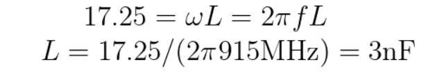
As we can see, the 50 matches the resistance, and we can convert the 17.25j, since the only reactive component is the inductor, using this equation:


Which matches as well. Voila!


Saturday, November 21, 2020

How to calculate output impedance in LTSpice

No idea why this isn't readily available on the web, but here it is. Caveat: I'm not an RF engineer, so I might be missing something basic.

Suppose you have a circuit in LTSpice such as follows:
So an AC signal is generated, passes through some black box, and you want to know the output impedance at Vout.  That is, you want to know the impedance of the black box.  For example, it could be that the black box is part of the RF transmit circuit and you want to know the impedance so you know what matching network to build to transform it into 50 ohms.

Step 1: Add an AC simulation directive at the frequency of interest, in this case 915 MHz.
Step 2:  Add a resistor to ground at Vout. The resistor value can be anything, but to avoid precision errors, probably best to put it roughly in same ballpark as anticipated real part of the impedance. Shown below:


Step 3: Simulate.  To make the example concrete, we'll use a simple circuit in place of the black box, of a resistor and inductor, though in practice the circuit could of course be much more complex:


And the simulation results will look like:


Now comes the fun part. First, we'll convert the current through our test resistor I(R1) from magnitude/phase into a complex quantity using the equation:

In our example,  plugging in 0.00514023 and -62.4433 produces I = 0.00237 - j 0.004557.
Current is the same thru the circuit so we can use Z = E / I (the complex form of R = V / I ) to find the total impedance of the circuit:


And then we subtract off our fake load of impedance 40 + 0j to get:


And in this particular case, since we know Zout consists of a resistor plus inductor, we can verify that the real part of Zout matches the resistor R2 (both 50 ohms) and we can use the imaginary part to verify the inductor value:


Voila!