Euclid’s shape is computationally generated, based on math resulting from a neat geometry insight. I quit my software engineering job four years ago to create it, and though it emerged from custom software, the cup itself is not digital in any way. No bluetooth, app or touchscreen. The Kickstarter page has a summary of the idea. Here I wanted to add a bit more detail about the project and how it came about.
My background is as a infrastructure software engineer. I was at Google and Facebook for 10 years building a number of distributed systems including GFS, Sibyl and Configerator.
I also love math and tinkering with things. Growing up, I spent a lot of (mostly voluntary) time in the basement, screwing around doing dumb stuff. What ever anyone says, it is a terrible idea to pull the spark plug wire off a running lawn mower with your bare hands.
One day I was baking in the kitchen and had a 2-cup measuring cup out and the recipe called for 1/4-cup. I felt like I should switch to a smaller measuring cup and for whatever reason stopped to wonder why. Why do smaller measuring cups seem better at measuring small amounts than larger measuring cups?
I realized it was about accuracy and that clearly defining measurement error would help in reasoning this through. Brace yourself, I’m going to get a bit technical, because understanding the problem was the key to solving it.
The problem
Let’s consider measurement error as the vertical distance between the target measurement line and the true height of the liquid. For example, when measuring 1-cup, you may think you hit the target line, but actually you overshot by 1mm because the measuring cup was not quite at eye level. Other possible reasons for missing the line include liquid sloshing, hand shaking, and the coriolis force (ok I’m kidding about that last one… I think).The graphic below shows an example of overshooting by 1mm:

The amount of extra liquid in the cup equals 1mm times the surface area of the liquid. Divide that by the target volume, and you have your fractional error (e.g., 5%).
If we assume that over-shooting (or under-shooting) happens just as easily at the top of a measuring cup as at the bottom, then that means the extra liquid height (1mm in the graphic) will be roughly the same at the top and the bottom.
Looking at the equation in the graphic, this means that measurement error depends primarily on the ratio of surface area to volume at the target line. Let’s call that the S/V ratio.
Here are a few interesting implications that may correspond to your intuition:
- Narrow measuring cups are more accurate than wide measuring cups.
- Small-capacity measuring cups are better at measuring small volumes because they are narrower. This answers the conundrum that started this whole quest.
- Cylindrical measuring cups measure smaller amounts less accurately than larger amounts. Why? Because the S/V ratio is larger at smaller amounts. This is why it’s hard to measure ¼-cup accurately in a 2-cup measuring cup. It’s also why larger measuring cups don’t have lines for ⅛-cup or 1-tablespoon or 1-teaspoon.
- Many measuring cups have sloped sides or are conical. All of these shapes have the same problem. The S/V ratio increases for smaller amounts, though not as quickly as in a cylindrical cup.
A natural question is, if narrow means more accurate, then why not use test tubes for measuring everything? Well, a test tube that holds 2-cups would be 10 feet high. I’m not sure about your cupboards, but 10-feet won’t fit in my cupboards, even if I rearrange things. But even if you bit the bullet and remodeled the kitchen to include a 10-foot high cupboard, the test tube would still be hard to use. A large fraction of whatever you’re measuring might end up stuck to the sides of the tube because there’s so much tube. So practical measuring cup design trades off accuracy for convenience.
Designing for the S/V ratio
We just observed that the ratio of surface area to volume (S/V ratio) is important to measuring accuracy, and that measuring cups today are less accurate measuring smaller amounts because the S/V ratio is larger for smaller amounts.That suggests that a solution would be a measuring cup shaped so that the S/V ratio is the same at every line marking. That would make it just as accurate measuring small amounts as large amounts. More precisely, it would be optimal in the sense that it minimizes the variance of error across all measurement amounts, for a chef who can get liquid to within k millimeters of each measurement line, for some constant k that varies with each chef's ability / effort.
Figuring out what kind of shape would have this property involves math. I started with some simplifying assumptions, like assuming the measuring cup is circular. It still was tricky and took me a number of months working on weekends. The math is not as complicated as it might sound. If I were honest, I’d say I didn’t know what I was doing initially and it took me a while to think about the problem the right way. But I’m not sure I’m ready to admit that :).
Below is an animation of how the surface area and volume changes. The Kickstarter page has a more detailed description of how the solution works. Below, I’ll talk about the process a bit.

The first design
There are many potential designs that have a constant S/V ratio. As I was developing the equations, I started playing with visualizations to understand the design space, first 2D via javascript and SVG, and then 3D using Blender, an open-source modelling program. Blender was cool partly because it has a python API, which made it possible to programmatically generate curves and surfaces that have the right geometry. The first rendering I have from this time is: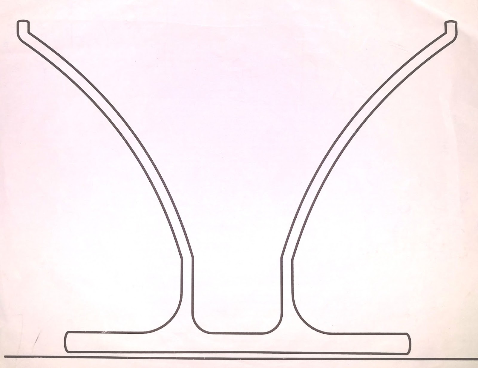
Bye-bye job
Around this point I left Facebook to work on this full-time. I knew I wanted to try starting some kind of company, I loved the measuring cup idea, and I also loved that it was far afield from what software engineers normally start companies around. Part of me liked the quizzical, surprised and somewhat distributed expression people got on their faces when I expressed my intentions.I thought of the measuring cup somewhat as a passion project and break from SWE, so I jumped into it with no business plan or customer research. Around this time I also incorporated an S-corp, filed patent applications and so forth.
Designing how to design
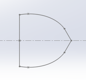
I started having industrial designer contractors help design the measuring cup and it quickly became apparent that there was a huge gap. Neither they nor their design software could couple design with the surface area & volume (S/V) geometry constraints in the way we needed.There were some expensive process failures here. They would design shapes that I didn’t know how to modify to obey the S/V constraints. The scheme I finally came up with was to separate design into three steps. First, the industrial designers created a cross-sectional closed curve of the measuring cup, such as:
I ran custom Python that replicated the curve as a sequence of ribs, positioning and scaling each rib according to the S/V constraints. For example:
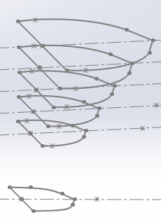 ----->
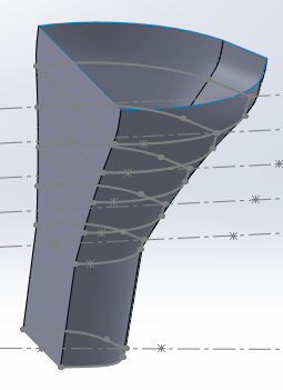
While 3D design software is terrible for designing with mathematical constraints, it is excellent for calculating surface area and volume of things. So once I had generated a shape, it was possible to write code to double check that the surface area and volume at every height was indeed what it was supposed to be.
Prototyping
I went through 25+ physical prototypes and countless 3D models. The bread & butter prototypes were 3D-printed in white plastic, sometimes via someone’s Makerbot, via 3D Hubs, a 3D printing marketplace. A much small number of high quality prototypes, including the one in the video, were milled from a block of PMMA. I wasn’t able to figure out a way to make transparent, food-safe prototypes economically.The original shapes were circular, such as
But it became apparent that industrial printing techniques could not print accurately on surfaces with compound curvature (i.e., non-zero Gaussian curvature, meaning it curves in two directions). So we switched to the flat-sided design you see on Kickstarter. This design also had a bonus that the markings much easier to read than on both our previous prototypes and most existing measuring cups.
Manufacturing
Talking to manufacturers was both thrilling and challenging. It was thrilling because they run heavy machinery that takes as input raw materials and usually some software and produces useful physical objects. As a software engineer, my best efforts just push around electrons.Talking to manufacturers was challenging because the domain knowledge is very different from that of software engineering. For example, there are engineers who specialize in something called Design For Manufacturing (DFM). You might think you come up with a design, prototype, do some testing and then hand it off to a manufacturer. Oh no no, my friend. If you don’t have in mind the technical constraints of manufacturing when you design, you probably are in for a surprise and some redesign work.
Manufacturers of course want business, but there is also a cost to them for talking with you. That includes the time of their in-house engineer to analyze your design, the risk that you might cause problems for them down the line because you’re inexperienced, and of course the opportunity cost of not working with someone who might place a larger order than you intend to.
I generally found manufacturers very polite and willing to both quote my designs and give useful feedback if there were issues. Through many iterations and discussions with many manufacturers, along with advice from DFM experts, the design was refined to the point where they now don't see any issues.
I’ll save a detailed discussion of manufacturing for another post, but below are two of the bigger limitations to injection molding. Limitations? To injection molding? Yup.
First, constant wall thickness is important. Injection-molding does not tolerate well large variations in thickness of the part. Partly this is because plastic shrinks as it cools and thicker sections shrink differently than thinner sections. Thick blobs of plastic also can have problems with air bubbles, and thick blobs also increase cost since the part needs to cool in the mold longer, which is time the machine can’t be making the next part.
Second, the way plastic flows when it's being injected matters. The way it works is this. The mold is a block of steel with a cavity into which hot, liquid plastic is squirted under high pressure. The plastic enters through a hole in the mold (called a “port”) and flows to fill the entire mold. As the plastic flows, it cools because the steel is relatively cold. The steel is cool partly to help the part solidify quickly so the machine can move on to make the next part. As the plastic cools, it becomes thicker and starts to harden. One reason the plastic enters under high pressure is so it fills the entire mold before it hardens.
The consequence of this is that sections of the mold that are further from the injection port are going to receive plastic that is cooler and thicker, and so the shape that the plastic can form is more limited. Also, shrinkage of plastic that is farther from the injection port differs from that of plastic closer to the injection port.
Luckily there are great software flow analysis tools out there that simulate how the plastic fills a mold and can predict what sort of issues might arise.
The rest
I skipped over a lot of detail about manufacturing and haven't even talking about printing and industrial inks. Nor have I talked about selecting a specific plastic and the range of material properties of plastics. Stay tuned or ask questions...